We use cookies to make your experience better. To comply with the new e-Privacy directive, we need to ask for your consent to set the cookies. Learn more.
Lapping Mesh Reinforcement: How to Calculate Overlap

Reinforcement mesh overlapping
Use of Reinforcement Mesh
Reinforcement mesh is commonly used in plate-type reinforced concrete (RC) members either horizontal, such as superstructure slabs and raft foundation slabs, or vertical, such as shear walls and core walls around stair cases or elevators. The use of such reinforcement is justified by the fact that it offers stiffness and strength in more than one direction within the member’s plan, which is exactly the reason for using plate-type members in construction.
Why Overlap Mesh Fabric?
Slabs and walls usually cover extended surfaces, but reinforcement mesh is typically provided by manufacturers in sizes ranging from 2.0m to 5.0m to facilitate transportation and positioning (Standard mesh sheets are 2.4m x 4.8m, and Merchant mesh sheets are smaller, at 3.6m x 2.0m).
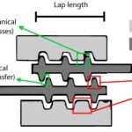
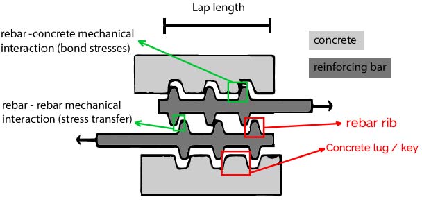
Therefore, during the construction phase, overlapping (or lap splicing) is necessary to ensure safe transfer of reinforcement stresses (tensile and compressive) between adjacent mesh modules (see Figure 1).
The engineer should make sure that the mesh bar extremities of the modules to be spliced are rigidly fastened together and wired. It should be mentioned that overlapping is the most common method for the transmission of forces from one reinforcing bar to another but not the only one. Arrangement of rebar mechanical couplers, or welding, are also available as methods, especially in cases of increased working place limitations.
It should be though stated that for the case of reinforcement mesh, lapping of bars is the only viable solution considering the number of rebars to be lapped as the other two methods require high amount of work per rebar.
Calculating Lap Length and Lapping Zones
The design lap length according to BS EN 1992, Eurocode 2 is given by the following formula:
l0 = α1α2α3α5α6 · lb,rqd ≥ l0,min
Where the coefficients a1, a2, a3, and a5 are introduced to account for the influence of bar shape, concrete cover, confinement due to transverse non-welded reinforcement and confinement by transverse pressure, respectively.
Coefficient a6 represents the influence of the percentage of lapped bars ρ1 within the considered zone and is equal to √ ρ1 / 25 but between 1.0 and 1.5.
The parameter lb.req is the required basic design anchorage length for the transmission of forces from reinforcing steel to concrete that is, according to EC2, equal to ⦰/4 ∙ σsd / fbd, where ⦰ is the rebar diameter, σsd. is the design stress of the reinforcement and fbd is the design bond stress.[/vc_column_text][vc_column_text]The minimum lap length l0.min is given by the following equation:
l0,min ≥ max{0.3 α6 lb,rqd; 15Φ; 200 mm}
Eurocode 2 suggests the reinforcement lapping to be staggered so as not to create a large zone of discontinuity that could potentially lead to member failure.
In the case of reinforcement mesh use, since this solution is not viable as the mesh modules come to the construction site as prefabricated, it is necessary to increase the lap length by attributing a higher value for a6 coefficient (for ρ1 > 50%).
When examining the amount of reinforcement lapped at a certain section, any laps located at a zone within 0.65l0 on either side of the section must be included. Moreover, in the case that the reinforcement mesh is subjected to compression (for instance bottom reinforcement in slab support zones) the lap length is larger than the case of reinforcement mesh subjected to tension (for instance, bottom reinforcement in slab mid-span zones). This is because in the case of compression coefficients a1, a2, a3, and a5 are set to unity, since bar shape, concrete cover, transverse reinforcement and pressure do not help in reducing the lap length, like it is for reinforcement under tension. Furthermore, in cases of reinforcement meshes to be spliced in zones of poor bond conditions, like for instance on the top face of RC slabs thicker than 250 mm, the lap lengths calculated with the above formulas must be multiplied by 0.7.
With regard to the arrangement of the lapping zones in plan (for horizontal members) and in elevation (for vertical members), the overlapping should not be performed in areas of high internal forces (e.g. bending moments) such as the base of shear walls where bending moment due to lateral (wind or seismic) actions is highest or RC slabs mid-span or support on beams (locations of peak moments under permanent loads).
Risks of Incorrect or Failure to Lap Mesh Fabric
In cases where the lap length is insufficient or non-existent the reinforcement stresses cannot be transferred adequately between the reinforcing bars. In this case, stress must pass from the reinforcing steel to the surrounding concrete.
Since concrete has lower stress capacity in both tension and compression compared to reinforcing steel, the material that determines the member behaviour is the concrete. Therefore, in zones subjected to tension large cracks are expected to appear while in zones subjected to compression concrete spalling is typically observed.
Such deficiencies can lead to dramatic consequences for the structural integrity of the structural members, especially in cases where limited redistribution can occur, such as in shear walls or columns (see Figure 2).
References
[1] J. Elwood, "Behavior and Modeling of Existing Reinforced Concrete Columns” EERI Presentation (https://www.1906eqconf.org/tutorials/SeisPerformExistConcrBldg_Elwood.pdf)
Related Products
-

-

-

-
Need Something A Bit Different?
Call Us On
01283 205 919